Assume you have a PC with Fedora Core 4 installed, acting as a router.
You have a local network and 2 ISPs.
Your local network
Network: 192.168.1.0/24
Router's IP for this network: 192.168.1.254
ISP 1
Network: 10.0.1.0/24
Router's IP for this network: 10.0.1.1
Gateway: 10.0.1.254
ISP 2
Network: 10.0.2.0/24
Router's IP for this network: 10.0.2.1
Gateway: 10.0.2.254
Configuring Interfaces
First, we configure interface eth0 for the local network:
# ifconfig eth0 192.168.1.254/24
Then we configure interface eth1 for ISP 1:
# ifconfig eth1 10.0.1.1/24
Next we configure interface eth2 for ISP 2:
# ifconfig eth2 10.0.2.1/24
That's all for interface configuration, next we'll setup routing.
Configuring Routing Tables
When configuring multiple ISP, we need a separate routing table for each of them.
We'll use the number 101 for the name of ISP 1's routing table.
And 102 for the name of ISP 2's routing table.
ISP 1 Routing Table
Make sure we start with empty table
# ip route flush all table 101
Add loopback network
# ip route add 127.0.0.0/8 dev lo table 101
Add local network
# ip route add 192.168.1.0/24 dev eth0 table 101
Add the network of ISP 1
# ip route add 10.0.1.0/24 dev eth1 table 101
Add default gateway for ISP 1
# ip route add default via 10.0.1.254 dev eth1 table 101
ISP 2 Routing Table
Make sure we start with empty table
# ip route flush all table 102
Add loopback network
# ip route add 127.0.0.0/8 dev lo table 102
Add local network
# ip route add 192.168.1.0/24 dev eth0 table 102
Add the network of ISP 2
# ip route add 10.0.2.0/24 dev eth2 table 102
Add default gateway for ISP 2
# ip route add default via 10.0.2.254 dev eth2 table 102
And we all set for ISPs routing tables.
Fixed or Balanced?
Next, we'll need to decide, how we will be using those ISPs?
Do we need split access, that is some of the computers on our local network will be using ISP 1, and some other use ISP 2?
Or we just want to use both ISP, utilizing it's connection and balance the load of them?
Case A: Split Access
Assume we want some of the computers on our local network to use ISP 1.
Their IP addresses are: 192.168.1.11 through 192.168.1.13
And some other will use ISP 2.
Their IP addresses are: 192.168.1.21 through 192.168.1.23
Thus we need to define ip rules, to classify the packets by source address.
Rules for ISP 1
# ip rule add from 192.168.1.11 table 101
# ip rule add from 192.168.1.12 table 101
# ip rule add from 192.168.1.13 table 101
Rules for ISP 2
# ip rule add from 192.168.1.21 table 102
# ip rule add from 192.168.1.22 table 102
# ip rule add from 192.168.1.23 table 102
That's it for ip rules, we just have one last step to do and all will work as expected, jump to SNAT below.
* Edit *
I forgot that this one also needs default gateway on the main table for packets originating from the router itself, here it is:
# ip route add default via 10.0.1.254
Case B: Load Balance
For this we don't need ip rules, we only need to setup default gateway on the main routing table so packets will be using each ISP in a balanced way.
Remove the existing default gateway
# ip route del default
And add a load balanced gateway
# ip route add default nexthop via 10.0.1.254 weight 1 nexthop via 10.0.2.254 weight 1
The key is to use same values for 'weight' parameter. You could guess what would happen if you put more weight on one gateway than the other.
SNAT
We need to map local ip addresses to public ip address that's been assigned by our ISPs.
So all packets that will be going out through ISP 1 on interface eth1 will be using 10.0.1.1 as their source ip address.
And all packets that will be going out through ISP 2 on interface eth2 will be using 10.0.2.1 as their source ip address.
For ISP 1
# iptables -t nat -A POSTROUTING -o eth1 -j SNAT --to 10.0.1.1
For ISP 2
# iptables -t nat -A POSTROUTING -o eth2 -j SNAT --to 10.0.2.1
And we all set.

April 11, 2009
March 14, 2009
How to Multi-Wan on Mikrotik RouterOS with Policy Routing part 2
Let's continue from where we left off.
So we got nth working to mark connections, good, but we're not finished with routing mark yet. We only did connection-mark, which will put subsequent packets related to the connections we have marked under the same connection-mark, but it has nothing to do with routing, for that we should add rules to set routing-mark so the connections will go out on different path.
We're finished with routing-mark step, in the following we should set source address of every packets that will go out to the internet to the correct one so they will get routed by our uplink providers.
2. Source NAT
Assume we're connected to the internet by two ADSL modems, where each have 1024kbits downstream bandwidth, modem A is connected to ISP 1 and its local IP address is 192.168.1.1,
modem B is connected to ISP 2 and its address is 192.168.2.1.
So we can configure our uplink interfaces as:
ether1 IP address: 192.168.1.2
ether2 IP address: 192.168.2.2
To have our connection packets routed correctly we must change their source IP to inteface's IP address depending on which interface they'll go out from, source NAT will do this for us and automatically translate them back when the answer packets are arrived on the router.
3. Default Routing For Each Routing Mark
Every packet that will go out from the machine will first consult the routing table to know which way it should go to reach its destination address. The default routing handles the packet destined to the internet.
The last rule will handle any other packets that neither marked with LINE1 or LINE2, such as packets originating from the router itself, like DNS requests.
From now on we will benefit from the combined bandwidths, when there are 100 connections initiated from our LAN, 50 will go out on ISP 1, and the other 50 go out on ISP 2. When we opened a web page, some connections will download images/data via modem A, and some others will download data/images via modem B. If it's not already obvious to you, a connection that is downloading file using regular browser download will just using either uplink, to use combined bandwidth when downloading single file use download manager like FlashGet, IDM, BitTorrent and the like.
This ended our journey of load balancing with policy routing on Mikrotik RouterOS.
So we got nth working to mark connections, good, but we're not finished with routing mark yet. We only did connection-mark, which will put subsequent packets related to the connections we have marked under the same connection-mark, but it has nothing to do with routing, for that we should add rules to set routing-mark so the connections will go out on different path.
/ip firewall mangle add chain=prerouting connection-state=new
dst-address=!192.168.0.0/16 nth=1,1,0 action=mark-connection
new-connection-mark=CONN1
/ip firewall mangle add chain=prerouting connection-mark=CONN1The newly added rules state that every packets with connection-mark CONN1/CONN2 should be marked with routing mark LINE1/LINE2 and when the rules matched stop traversing the next rule in prerouting chain (passthrough=no).
action=mark-routing new-routing-mark=LINE1 passthrough=no
/ip firewall mangle add chain=prerouting connection-state=new
dst-address=!192.168.0.0/16 nth=1,1,1 action=mark-connection
new-connection-mark=CONN2
/ip firewall mangle add chain=prerouting connection-mark=CONN2
action=mark-routing new-routing-mark=LINE2 passthrough=no
We're finished with routing-mark step, in the following we should set source address of every packets that will go out to the internet to the correct one so they will get routed by our uplink providers.
2. Source NAT
Assume we're connected to the internet by two ADSL modems, where each have 1024kbits downstream bandwidth, modem A is connected to ISP 1 and its local IP address is 192.168.1.1,
modem B is connected to ISP 2 and its address is 192.168.2.1.
So we can configure our uplink interfaces as:
ether1 IP address: 192.168.1.2
ether2 IP address: 192.168.2.2
To have our connection packets routed correctly we must change their source IP to inteface's IP address depending on which interface they'll go out from, source NAT will do this for us and automatically translate them back when the answer packets are arrived on the router.
/ip firewall nat add chain=srcnat out-interface=ether1 action=src-natThat's it for source NAT, in the following we'll be configuring the routing table which will be the main reason why our packets get routed to different path each time.
to-addresses=192.168.1.2
/ip firewall nat add chain=srcnat out-interface=ether2 action=src-nat
to-addresses=192.168.2.2
3. Default Routing For Each Routing Mark
Every packet that will go out from the machine will first consult the routing table to know which way it should go to reach its destination address. The default routing handles the packet destined to the internet.
/ip route add gateway=192.168.1.1 routing-mark=LINE1The first and second rules will handle packets having routing-mark LINE1 and LINE2, so a connection marked with LINE1 will go out on modem A and the others marked with LINE2 will go out on modem B, it's because nth that make it possible to flip flop path like this.
/ip route add gateway=192.168.2.1 routing-mark=LINE2
/ip route add gateway=192.168.1.1,192.168.2.1
The last rule will handle any other packets that neither marked with LINE1 or LINE2, such as packets originating from the router itself, like DNS requests.
From now on we will benefit from the combined bandwidths, when there are 100 connections initiated from our LAN, 50 will go out on ISP 1, and the other 50 go out on ISP 2. When we opened a web page, some connections will download images/data via modem A, and some others will download data/images via modem B. If it's not already obvious to you, a connection that is downloading file using regular browser download will just using either uplink, to use combined bandwidth when downloading single file use download manager like FlashGet, IDM, BitTorrent and the like.
This ended our journey of load balancing with policy routing on Mikrotik RouterOS.
March 13, 2009
How to Multi-Wan on Mikrotik RouterOS with Policy Routing
This guide will show you how to do load balancing on Mikrotik RouterOS with policy routing method. Load balancing is also known as bandwidth aggregation with the purpose to combine several uplink connections so we can benefit from the combined bandwidths, an example of two 512kbits ADSL connections when combined together will get us 1024kbits theoritically.
There are several methods to do load balancing on multiple ISP/uplink/WAN. One of those methods is interface bonding, it's done by combining several interfaces that are used for uplinks -- that is interfaces that are connected to the ISPs -- under a newly created interface acting as a master, thus interfaces that are combined under it will be in the role of slaves. The master interface will then be assigned an ip-address and will communicate with another master interface on the ISP side, every packets going through the master will then be distributed to the slaves one after another in the case it's configured to act in round-robin fashion. But the requirement of configuring master interface on the ISP side often made this method not our option.
So we are left with client side configurations which mean configurations that take place only on our routers. There are several ways to configure load balancing, but this time let's just choose policy based routing. The first time I hear about this method it's sounds like complicated when in fact it's pretty simple. We basically just need to do several steps:
Let's make an example case. Assume we have a Mikrotik router with 3 ethernet ports: ether0, ether1 and ether2. ether0 is connected to our LAN, ether1 to ISP 1 and ether2 to ISP 2.
And we want to load balance connections to the internet so each new connection/session originating from our LAN will flip flop path between ISP 1 and ISP 2. We let Mikrotik nth feature do its job.
Nth have three parameters, they are every, counter, and packet, on rule 1 we set those parameters to 1, 1, 0 for every, counter, and packet respectively, and on rule 2 we set them to 1, 1, 1.
Let's take it slowly and learn how nth works. The counter parameter will begin with zero, when one of our rule is matched the counter will incremented by one, and when it reach every the counter will resets back to zero. Our rule will match if packet equals counter. Study the chronology of nth states:
But first, do not confuse the value of the counter with the counter ID, when we stated on the above rule nth=1, 1, 0 what we really meant is counter ID = 1 not the value of the counter = 1, because there are 16 counters on Mikrotik and we can choose which one we would like to use, their ID is between 0 and 15 inclusively, and on the above example we chosed 1. So on the following when I say counter = 0 it will mean counter ID 1 that have value of zero and so on.
Assume the Mikrotik has just started and nth's counter = 0.
Then a new connection coming from the LAN, when it reach rule 1 the packet matched because the value of packet equals counter, and so counter is incremented by one. So now counter = 1.
Then a new connection coming from the LAN again, when it reach rule 1 the packet didn't match because packet (0) not equals counter (1), so Mikrotik bypassed the rule and go to rule 2 which matched the packet because packet in rule 2 equals counter.
At this time the counter shall be incremented by one, but Mikrotik found out that counter equals every and instead reset the counter back to zero, so it starts all over again.
The counter life cycle is: 0, 1, 0, 1, 0, 1, 0 and so on.
The rule that matched is: rule 1, rule 2, rule 1, rule 2 and so on.
I hope you all understand nth by now, I tried hard to explain because there are so many people that still didn't understand even though they have read Mikrotik documentation on nth.
We got more to explain but let's continue on another post... Oh I'm not cruel, I'm just tired.
There are several methods to do load balancing on multiple ISP/uplink/WAN. One of those methods is interface bonding, it's done by combining several interfaces that are used for uplinks -- that is interfaces that are connected to the ISPs -- under a newly created interface acting as a master, thus interfaces that are combined under it will be in the role of slaves. The master interface will then be assigned an ip-address and will communicate with another master interface on the ISP side, every packets going through the master will then be distributed to the slaves one after another in the case it's configured to act in round-robin fashion. But the requirement of configuring master interface on the ISP side often made this method not our option.
So we are left with client side configurations which mean configurations that take place only on our routers. There are several ways to configure load balancing, but this time let's just choose policy based routing. The first time I hear about this method it's sounds like complicated when in fact it's pretty simple. We basically just need to do several steps:
- Set routing mark of packets to identify their path later, ie. mark with 101 for packets that will go out on line 1, 102 on line 2 and so on.
- For every interface that connected to ISP, source NAT every packets that going through it to the correct ip address.
- Add default routing for each routing mark that we set earlier.
Let's make an example case. Assume we have a Mikrotik router with 3 ethernet ports: ether0, ether1 and ether2. ether0 is connected to our LAN, ether1 to ISP 1 and ether2 to ISP 2.
And we want to load balance connections to the internet so each new connection/session originating from our LAN will flip flop path between ISP 1 and ISP 2. We let Mikrotik nth feature do its job.
/ip firewall mangle add chain=prerouting connection-state=new
dst-address=!192.168.0.0/16 nth=1,1,0 action=mark-connection
new-connection-mark=CONN1
/ip firewall mangle add chain=prerouting connection-state=newThose lines basically say: for every new connection (connection-state=new) with destination to the internet (dst-address=!192.168.0.0/16) do mark the connection (action=mark-connection) with CONN1 (new-connection-mark=CONN1) if rule 1 matched, otherwise mark connection with CONN2 if rule 2 matched.
dst-address=!192.168.0.0/16 nth=1,1,1 action=mark-connection
new-connection-mark=CONN2
Nth have three parameters, they are every, counter, and packet, on rule 1 we set those parameters to 1, 1, 0 for every, counter, and packet respectively, and on rule 2 we set them to 1, 1, 1.
Let's take it slowly and learn how nth works. The counter parameter will begin with zero, when one of our rule is matched the counter will incremented by one, and when it reach every the counter will resets back to zero. Our rule will match if packet equals counter. Study the chronology of nth states:
But first, do not confuse the value of the counter with the counter ID, when we stated on the above rule nth=1, 1, 0 what we really meant is counter ID = 1 not the value of the counter = 1, because there are 16 counters on Mikrotik and we can choose which one we would like to use, their ID is between 0 and 15 inclusively, and on the above example we chosed 1. So on the following when I say counter = 0 it will mean counter ID 1 that have value of zero and so on.
Assume the Mikrotik has just started and nth's counter = 0.
Then a new connection coming from the LAN, when it reach rule 1 the packet matched because the value of packet equals counter, and so counter is incremented by one. So now counter = 1.
Then a new connection coming from the LAN again, when it reach rule 1 the packet didn't match because packet (0) not equals counter (1), so Mikrotik bypassed the rule and go to rule 2 which matched the packet because packet in rule 2 equals counter.
At this time the counter shall be incremented by one, but Mikrotik found out that counter equals every and instead reset the counter back to zero, so it starts all over again.
The counter life cycle is: 0, 1, 0, 1, 0, 1, 0 and so on.
The rule that matched is: rule 1, rule 2, rule 1, rule 2 and so on.
I hope you all understand nth by now, I tried hard to explain because there are so many people that still didn't understand even though they have read Mikrotik documentation on nth.
We got more to explain but let's continue on another post... Oh I'm not cruel, I'm just tired.
March 08, 2009
How To Easily Manage Bandwidth In Linux
An Easy Method to Control Bandwidth on Linux Using tc (traffic control)
I'll show you how to easily manage your precious internet bandwidth in Linux. The distribution of Linux that I'm using here is Fedora Core 4, so if you happen to have any trouble with the following information and script then it just might be caused by our different system if you're using any other than Fedora Core 4.
It's very frustrating to experience crawling slow internet connection. Sometimes you just have a question in your head that needs answer fast and like always you decide to consult the good old Google. So you fired up your Mozilla and type in the term in the search bar then stomp enter, but the progress status keeps circling while you stare blankly at the white screen in front of you. You keep on waiting hoping the screen instantly filled with Google image and its search box, but three minutes just passed and the white screen just won’t go away.
What actually has happened? The admin of the network you’re on told you it’s 128/1024 kbps (kilobits per second, for Kilobytes it would be capitalized K as in Kbps) upstream/downstream connection and it’s 1:00 AM where only you and another one sleepy staff are on the network, it shouldn’t be lagged this bad when there’s only few people on the line. So you asked the Network Administrator who happen to be tinkering with something in the room just across you; only to found out that the upstream bandwidth has all been sucked up by the uploading process initiated by that one sleepy staff, apparently he’s uploading something big to his email. This shouldn’t have happened if you have QoS controller running on the network router. The QoS stands for Quality of Service which basically means Bandwidth Management.
Linux have already a built-in bandwidth controller program called tc. To understand how tc works you must have a mental image of a tree structure, a tree structure goes like this:
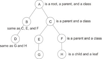 All the circles are called nodes. There are three types of nodes. The first is root, it’s the mother of all nodes, and no other nodes came before it. The second is parent; parent is a node that has other nodes under it, which are its children. And the last one is leaf, which means no other nodes under it.
In tc we just basically defining nodes. There are another two types of nodes in tc, they are class and qdisc. Class is a node that has children which also make it as a parent, apart as a parent the main role of a class is limiting bandwidth. Think of a class as a valve, you can control the speed of Ethernet packets with it. qdisc stands for Queuing Discipline, it’s always a leaf node, and its main role is just that, queuing packets. In our tree structure image the class can have positions at A, B, C, E, F, and the qdisc at D, G, and H.
Here the fun begins. To create a working bandwidth management configuration in tc, we do four main things:
- Attach the root of our nodes to an Ethernet interface. If you don’t know an interface just think of it as a digital form of your LAN card and you refer to it as eth0, eth1, or eth2 according to the number of your LAN cards.
- Define classes which control the speed of Ethernet packets.
- Define qdisc for each class that doesn’t have any children.
- Define rules in mangle table to mark packets with a number which is the id of the class that we want the packet to go to.
To make your life easier I just wrote a script that you can immediately use with a little configuration, here it is:
Save the following in a file named setband
Don't forget to edit the UPSTREAM, DOWNSTREAM, and MARKING sections to fit your needs.
Save the following in a file named setband
---BEGINNING OF FILE---And save the following in a file named bandconf
#!/bin/bash
#################
### FUNCTIONS ###
DEV=
QDISC=1
root() {
DEV=$1
tc qdisc del dev $DEV root
tc qdisc add dev $DEV root handle $QDISC:0 htb
}
class() {
PRIO=
if [[ -n $5 ]]; then
PRIO="prio $5"
fi
tc class add dev $DEV parent $QDISC:$1 classid $QDISC:$2 htb rate $3 ceil $4 $PRIO
}
leaf() {
class $1 $2 $3 $4 $5
tc qdisc add dev $DEV parent $QDISC:$2 handle $2:0 sfq perturb 5 quantum 1500
tc filter add dev $DEV parent $QDISC:0 protocol ip handle $2 fw flowid $QDISC:$2
}
##############################
### RUN USER CONFIGURATION ###
name=`basename $0`
#path=`echo $0 | sed -e s/$name//`
path=`dirname $0`
source $path/bandconf
---END OF FILE---
---BEGINNING OF FILE---After you created the files change their mode so you can execute them:
# upstream interface
UPIF=eth0
# downstream interface
DNIF=eth1
# upstream bandwidth
UP=128kbit
# downstream bandwidth
DN=1024kbit
#-----------------------------------------------------------------
# UPSTREAM - eth0 connected to your ISP
root $UPIF
# this class is a child of root, root have id of 0
# this class id is 1
class 0 1 $UP $UP
# don't be fooled by the following leaf statement.
# it's actually a call to a function named leaf which
# creates a htb class with specified bandwidth limit
# then creates a qdisc under it with a type of sfq qdisc,
# and finally creates a filter on the root to direct packets
# marked by iptables to the newly created class
# (see the content of setband file)
leaf 1 101 32kbit 64kbit
# limit speed of packets marked with 102 to 16kbit/s
# and when there are more bandwidth in its parent allow
# it to borrow up to 50kbit/s
leaf 1 102 16kbit 50kbit
#-----------------------------------------------------------------
# DOWNSTREAM - eth1 connected to your LAN
root $DNIF
# this class is a child of root, root have id of 0
# this class id is 2
class 0 2 $DN $DN
# limit speed of packets marked with 101 to 256kbit/s
# and when there are more bandwidth in its parent allow
# it to borrow up to 1024kbit/s
# 101 here is not the same as 101 in upstream configuration
# because it rooted on different ethernet interface
leaf 2 101 256kbit 1024kbit
# limit speed of packets marked with 102 to 256kbit/s
# and when there are more bandwidth in its parent allow
# it to borrow up to 768kbit/s
leaf 2 102 256kbit 768kbit
#-----------------------------------------------------------------
# PACKETS MARKING
OURNET=192.168.0.0/16
# these rules mark packets with upstream direction
iptables -t mangle -A FORWARD -s 192.168.10.1 -d ! $OURNET -j MARK --set-mark 101
iptables -t mangle -A FORWARD -s 192.168.10.2 -d ! $OURNET -j MARK --set-mark 102
# these rules mark packets with downstream direction
iptables -t mangle -A FORWARD -d 192.168.10.1 -s ! $OURNET -j MARK --set-mark 101
iptables -t mangle -A FORWARD -d 192.168.10.2 -s ! $OURNET -j MARK --set-mark 102
---END OF FILE---
chmod +x setband bandconfThen edit /etc/rc.local and add the following line so the configuration takes effect every system reboot:
/etc/band/setbandChange /etc/band if you put the files on different directory.
Don't forget to edit the UPSTREAM, DOWNSTREAM, and MARKING sections to fit your needs.
May 21, 2008
How to disable traceroute using iptables
To disable traceroute coming from Linux box (tested on Fedora Core 4):
# iptables -t filter -A OUTPUT -p icmp -m icmp --icmp-type port-unreachable -j DROP
And to disable traceroute coming from Windows box (tested on Windows XP Professional):
# iptables -t filter -A OUTPUT -p icmp -m icmp --icmp-type echo-reply -j DROP
# iptables -t filter -A OUTPUT -p icmp -m icmp --icmp-type port-unreachable -j DROP
And to disable traceroute coming from Windows box (tested on Windows XP Professional):
# iptables -t filter -A OUTPUT -p icmp -m icmp --icmp-type echo-reply -j DROP
Subscribe to:
Posts (Atom)
